There are two kinds of flash SIMMS for the Webpal. The
first contains a single 29F800B chip and has 1MByte arranged as 512K by 16
bits. The second chip has two SIMM chips and is 2MByte arranged
as 512K by 32 bits. The programmer described here is for the
1MByte SIMM. Its unclear how useful this still is
since people are coming up with ways to program the FLASH directly using
the Webpal, but here is the information.
To program the flash you need:
- 19 address lines (outputs)
- 16 data lines (bidirectional)
- 3 control lines (CE, OE, WE) (outputs)
There are several of ways to come up with this many lines you can control.
I used a combination of a PIC16F877 prototype board and a second PC board
containing three HCT573 latches to come up with all those lines.
If you had a PC with a board(s) with lots of parallel input and output bits,
one could use that also as the basic for a programmer. Another
possibility would be to build the second PC board using I2C latches.
The programming itself simply consists of writing special sequences to
special addresses and wiggling the CE, OE, WE lines. You
also need to be able to read the data bus to check for completion of the
write operations. Get a data sheet for the flash chip
from the web to see the programming details.
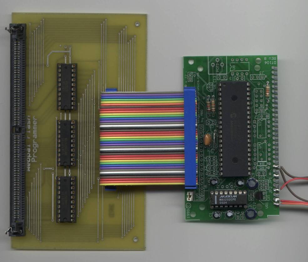
The flash programmer I built consists of two printed circuit boards.
Here is a picture of it.
- A DT-106 PIC prototype board (available from www.dontronics.com) in which
I installed a PIC16F877 PIC chip. I also populated the board
with a MAX232CPE to provide a serial interface. The 40 pin header
on the board connects to the second board described below. You should
install the following components: U1, U2, C1, C2, C3, C4, C12, C13,
R6, JP4, X1, C6 & C5 (if you use a xtal for X1, I used a ceramic resonator),
R1, R2, R3 (I used a jumper), VR1, J1. This is pretty much the
minimal set of parts for this board. Use a 20MHz resonator
or crystal. The DT106 also needs a ~ +8VDC power source and an RS-232-C
connector. If you leave out the regulator on the board, you could
power it all with a 5VDC source.
- The second board is simply a 40 pin header, three HCT573 latches,
and a 72 pin SIMM socket. The HCT573 latches provide the 19 latchable
address lines that I can set/clear from the PIC chip. The
16 bits of bidirectional data and three control lines come directly from
various PIC pins. This board could be hand-wired but
I didn't relish doing all that hand wiring so I made a double-sided PC board using the ExpressPCB service. This
costs a lot more (around $105 for two boards) but was much more fun that
all that wiring. Here is the PC board
layout. I do not have a schematic of this board,
so if you are hand wiring it, you'll need to print out the PC board and use
it as the reference. Here is a pdf file that shows the component layout.
The serial input of the PIC chip is driven at 115.2K from my Linux system.
I wrote a simple Linux application that reads binary files and writes them
to either location 0 (if its the boot program) or 64K (if its the Linux zImage)
file. It call also write all of the flash and dump the flash
if you want to preserve your current Webpal code. There
is a simple set of commands that the Linux application uses to communicate
with the PIC chip. I've begun to duplicate the flash
progamming code in the my booting code so in the future you could use the
Webpal itself to update the zImage file using the same Linux program.
A 40 pin cable is used to connect the two boards together.
PIN1 in each case is marked by the square PC pads..
Here are the sources. This
consists of:
flashpgm.c is the C source for the PIC chip. I used the C2C
compiler for Linux for the PIC chip.
flashpgm.hex is the hex output of the above program that can be directly
programmed into the PIC chip. It does not include the configuration
bits, so set them to the appropriate value (I used 0x3ff2).
wpflash.c is the Linux application to drive the programmer.